Newer devices
Starburst Turret
How to build things like this
Robot
About Me
Hexapod Robot Leg, Mod 1
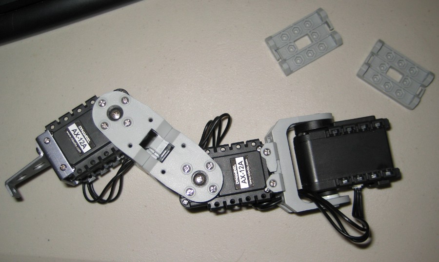
Because inexpensive hobby servos proved inadequate, I built a new hexapod leg using the AX-12 servo made by the Korean company Robotis. The AX-12 servo is designed specifically for robotics: it's controlled with an RS-232 serial link instead of PWM, so you can get data from it such as current position, speed, and a rough estimate of torque. It also allows you to tweak its position control characteristics (by setting the gain and deadband for the proportional controller), so you can make its position control as "loose" or "tight" as you want.
At $45, an AX-12 is pricier than a hobby servo, but it's easily worth it for making a robot leg. It's made to be built with: on the opposite side of the servo from the "horn" is a place to mount an included plastic bearing, which allows the (included) plastic actuator frame to form a strong rotating joint with no additional parts. Each servo also comes with a plastic mounting frame (top of the picture) which can attach to the actuator frame using included bolts. As shown above, you can build a leg using only the parts included with 3 AX-12s. (The only exception is that I made the "foot" on the left side of the picture by using a foot bracket from Crustcrawler, but I plan to replace it with a longer custom foot piece.)
You talk to the AX-12 using a half-duplex RS-232 serial bus, meaning that when you're done transmitting to the servo, you have to disconnect your transmitter by some means and use the same wire to listen for the servo to talk back. To do this, Robotis offers a $50 interface device called USB2Dynamixel that connects to a computer over USB and forwards commands to the servo bus. It works for any of Robotis's "Dynamixel" series of servos, which includes some more expensive, higher-torque models in addition to the AX-12. It has libraries for most programming languages, so I recommend it. (I also tried talking to the AX-12 using a PIC as a PC-to-servo interface, which also worked but ended up being less convenient. Code for that is below.)
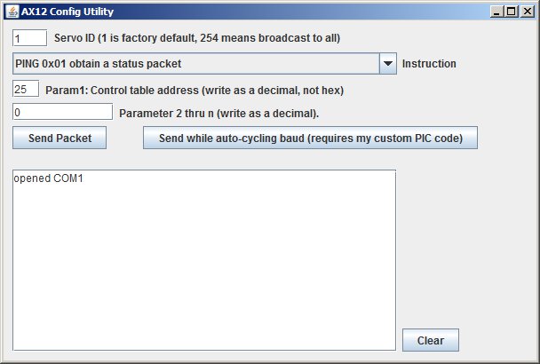
As discussed in the Crustcrawler.com tutorial on the USB2Dynamixel, the best way to test it out is with the Dynamixel Configurator program.
Using the USB2Dynamixel Java API, I updated my Java inverse-kinematics program to use the new leg. The result is excellent leg control with none of the oscillations I saw with hobby servos (of course, the job is a little easier because the AX-12 leg is shorter and lighter, but I think the ability to tweak the AX-12 control system will make it work well for longer legs also). In the video below, my program transmits a sequence of foot positions to move the foot in a circle:
AX-12 Robot Leg Test Video (2.8 MB)
The Java code that performs the inverse kinematics and outputs commands to the USB2Dynamixel is below. It's still a work in progress; if you use it, email me and I'll be happy to help you understand it:
- Complete Eclipse project: SpiderRobot_withUSB2Dynamixel.zip
The project uses the Eclipse development environment and should work out of the box (in Eclipse, open it using File/Import...). But for reference in other projects: getting the USB2Dynamixel to work in a Java program basically involved downloading and installing the USB2Dynamixel SDK (make sure you get v1.03 or later, as there's an earlier version that doesn't have the Java library. Or use my mirror.) Then I copied their dynamixel_jni.dll into the root of my project, and copied dynamixel_jni.java into the <project>/src folder (it needed to be just loose in the src folder; putting it into package-name subfolders seemed to mess it up).
The USB2Dynamixel library uses the Java Native Interface (JNI) which means Robotis wrote their code in C++ and compiled it into the .dll file. Therefore you have to use the methods in dynamixel_jni.java to call the C++ functions inside the .dll. It's a little messy but it works. (Also, you'll notice my project still includes the RxTx library that I used with my previous hexapod leg, but it's not needed if you just want to use USB2Dynamixel.)
For editing my program's GUI, I used Google's WindowBuilder plugin to Eclipse; I recommend it as well.
Now that the leg is working well, my next step is to attach some force-sensing resistors and do some fancy robotics stuff. More on that in the future.
Appendix: Talking to the AX-12 using a PIC instead of the USB2Dynamixel
I highly recommend not doing this and instead using the USB2Dynamixel; the following is just a resource for anyone who needs it.Before coming to my senses and paying the $50 for the USB2Dynamixel, I talked to the AX-12 using a PIC18F26K22 microcontroller as an interface between my computer's normal serial port and the servo's half-duplex serial bus. Basically the computer forms the Dynamixel packet (the format is given in the AX-12 datasheet) and sends the packet to the PIC through one of the PIC's serial ports. The PIC forwards each byte to the servo (using the other of its two serial ports), while monitoring the bytes to detect the end of the packet. When it detects the end of the packet, it turns off its UART transmitter, making the pin switch to high-impedance, and enables its UART receiver (which was connected to the same line). It then forwards whatever it receives to the computer.
- Here's the PIC code: serialpassthru.c
- and, in the form of an MPLAB X IDE project: serialpassthru.X.zip
The circuit is simple: Connect the computer's serial port, through a MAX232 converter chip, to RB6 and 7 (which are USART 2 of the PIC). Tie together RC6 and 7 (which are USART 1 of the PIC), and connect them to +5V through a 10K pullup resistor, and connect them to the AX-12 data line.
Power the PIC and the AX-12 and it should work. (I recommend 0.1-inch breakaway header strips for connecting the AX-12 cable connectors to a solderless breadboard, but you can also just jam 22AWG wire into them, or cut and solder in to them.)
The PIC code configures the servo-side USART to operate at 1Mbaud, which doesn't seem to be supported based on a read of the PIC18F26K22 datasheet but seems to work anyway. The datasheet is also a little ambiguous about the ability to turn off the TX pin while still using the RX pin, but that also seems to work. And, finally, note that the code assumes the computer's baud rate is less than or equal to the servo baud rate (i.e. it doesn't buffer transmissions from the computer; it just forwards them, so you can't talk to a servo at a lower baud than the computer uses. This is easy to fix by adding a buffer in the unlikely event that you need that ability). I tested the code with the computer at 115200 baud and the servo at 1Mbaud (the default).
The PIC just forwards bytes, so the computer needs to generate the packets. Here's a graphical Java program (using the RxTx serial-port library) which can generate Dynamixel packets and displays any received packets. You'll need to reference the AX-12 datasheet list of control table addresses while using it.
- Eclipse project: AX12config.zip
- Runnable JAR program: AX12config.jar
Again, for general experimentation I recommend NOT using a PIC and instead using the USB2Dynamixel, which is more widely used and has good libraries. The serial-port-to-PIC-to-servo solution is just provided here in order to spare anyone else the effort of redeveloping it if your application needs it. (I spent an inordinate amount of time debugging it; hours were wasted discovering that, unlike a PIC, an AX-12 only receives messages when they're sent at its transmission baud rate. I also initially missed the fact that the packet checksum must be inverted. Both of these errors yield a silent AX-12 with no feedback on the problem. But now you can avoid my pain.)