Newer devices
Starburst Turret
How to build things like this
Robot
About Me
Getting Started with PICs
This PIC C programming tutorial will guide you to get a simple C program working on a PIC microcontroller, including setup of the programmer. The tutorial uses C programming with the Microchip C18 compiler, and the relatively newer PIC18F1320 chip. That chip has analog-to-digital converters, serial communications ability, and other nice peripherals.If you haven't used microcontrollers before, they're a great way to add intelligence to your projects. They're just tiny, cheap computers. Microchip PIC microcontrollers are cheap and highly capable, but they're aimed at production devices, so they're a little harder to get started with and understand than microcontrollers that are aimed at hobbyists, such as the BASIC Stamp series. I recommend starting with the BASIC Stamps first unless you're pretty confident in your abilities. (The Arduino microcontroller is similarly easy to learn/more expensive, and is apparently the trendy microcontroller to use for DIY projects, but I haven't personally tried it.)
Anyway, here's a simple "hello world" type programming guide for PIC C programming:
Install the required software:
<Update: the instructions below were written for the MPLAB IDE. The newer version is the MPLAB X IDE and is far superior. If you use MPLAB X, you don't need to download the MPLAB C Compiler as it's already included. Also some of the details of starting a new project below will be different or unnecessary, so just go through its wizard. The C files below will still work though. I'm leaving this page up in case anyone is referencing it, but I recommend finding a newer guide than this one-- these days, Adafruit and Sparkfun far surpass my personal website in quality of guidance.>- Download and install MPLAB IDE. (It's best to install this before the C compiler.)
- Download and install MPLAB C Compiler (a.k.a. C18 compiler). Get the free "Standard-Eval Version." Remember where you install it. Also download the "MPLAB C18 Libraries Documentation" and the "C Compiler Getting Started" documents on the same page. (When installing, tell it to "Update the MPLAB IDE" if it gives you the option.)
Start a new project:
- In MPLAB IDE, go to Project/Project Wizard...
- Tell it to use the PIC18F1320 device.
- It will next ask you what language you want to program in. The default is assembly, which is not what we want. So under "Active Toolsuite" choose Microchip C18 Toolsuite. When you choose that, you may see that it doesn't know where some files are. If so, you need to tell it where you installed C18. It asks for 4 files:
- MPASM Assembler is in <C18 installation directory>\mpasm
- The other 3 files are in <C18 installation directory>\bin
- Click Next. Under "Create New Project File," click Browse, and choose a folder where you're going to save all of your work. Type a file name for your project, such as "testproject", and click Save.
- Click Next. We'll skip the step of "Add Existing Files to your project," we'll do that later. So click Next again, and click Finish.
- You'll now see a fairly blank workspace.
- Go to Project/Build Options/Project...
- Under "Directories," set the "Include Search Path" to <C18 installation directory>\h
- Set the "Library Search Path" to <C18 installation directory>\lib, and click OK.
- If you have problems, the "C Compiler Getting Started" document that I had you download has more detailed instructions (A few user interface parts may have different names, depending on MPLAB version).
Add files to the project:
- First we need to choose the "Linker Script" for our PIC model. This is a file that contains device specific information that the C18 compiler will need. From our perspective, we just choose it and forget it. Look at the tree of folders displayed under "testproject.mcp." Right-click on "Linker Script" and choose "Add Files..." Navigate to <C18 installation directory>\bin\LKR and choose the file "18f1320_g.lkr".
- Then we add the actual C source code. First, download, unzip, and copy the "tutorial1.c" file below into the directory where you saved your project. Then right-click on "Source Files" under "testproject.mcp." Choose "Add Files..." and select tutorial1.c. It will appear under "Source Files." Double-click it to open it.
Compile the project
Go to Project/Build All. If all goes well, a window will come up saying "BUILD SUCCEEDED." If you go to your project's folder, you should see a file called "testproject.hex." Congratulations! You've successfully compiled a PIC program. (If there were problems and it said "BUILD FAILED," read the text above that to see what the problem is. You may have skipped one of the project setup steps above, especially if the error is about not being able to locate something. Also check the C18 Getting Started Guide.)Acquire a PIC
You can get up to 4 free samples from the Microchip web page (make sure you get the PDIP packages; others won't work on a breadboard). You can also download the 18F1320 datasheet, which includes the pin names and other information that you'll need when you start writing your own programs.Get the program onto the PIC
The testproject.hex file contains everything - both the program and all configuration information that the PIC needs. There are various ways to get that file into the PIC. I originally used a cheap third-party "JDM programmer" from Ebay. Those require you to have a serial port on your computer though, which most PCs don't have anymore. They generally won't work with USB-to-serial converters either, because most USB-to-serial converters are cheap and don't actually produce the standard serial port voltage levels.So, I recommend just buying one of Microchip's official USB-based programmers. The current most popular is the PICkit 3 (you just need the $45 programmer itself for our purposes, not the development boards, etc.) To connect the PICkit 3 to the PIC, look at the PICkit 3 User's Guide; it has a pinout of the programming connector. Connect each pin of that to the corresponding PIC pin, using the PIC pinout from its datasheet. Here is an illustration of the connections. You can buy header connectors to connect in to the PICkit's programming connector, or you can just jam 22-gauge wire into the sockets and tape everything in place. I leave the wires connected properly on a spare breadboard, and just put the PIC in that breadboard to program it. The MPLAB IDE can connect to the PICkit 3 directly to program the PIC.
Test the PIC program
The next thing to do is put the PIC in a circuit and see if it really works. The circuit below will do that. I strongly recommend you build the circuit using a solderless breadboard, as discussed on my how-to-build-electronics page. You’ll want some 22-gauge wire, from the internet or Radio Shack, for making connections on the breadboard.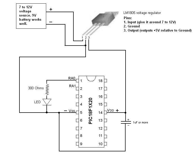
Here's a brief description of the circuit:
The LM1805 voltage regulator takes between about 7 and 12 volts at its input, and outputs a tightly-controlled 5 volts at its output. It needs a capacitor on the output to help it keep a steady voltage. (That information is from the datasheet.) A good source of the input voltage is a 9V battery, or a DC wall power supply from an old phone, LAN router, or other consumer electronics. You can buy the clip-on connectors to connect to 9V batteries. For a DC wall power supply, use your ingenuity (I usually just solder 22-gauge wires to the existing wires.).
The PIC - You can find out which pins are which from the picture in the PIC18F1320 datasheet. For now, we're just using the + and - power connections, and pin RA0. Pin RA0 is a general input/output pin. The tutorial code configures it as an output. It alternates its output between a logic "1" (5 volts) and logic "0" (0 volts).
The LED and resistor are used to see what RA0 is doing (you can use a multimeter instead if you want). When RA0 is at 5V, the LED will light. (The resistor limits the current to about 10mA, which is typical for LEDs. Anywhere in the 200-500 ohm range should get it to light.) If you want, you can also put another LED and resistor between the + and - lines, to indicate when the circuit is powered.
The capacitor, is discussed above, is needed on the output of the voltage regulator. The PIC also needs a capacitor across its inputs. If you don't give it one, it shows weird behavior, restarts, etc. If you do get weird behavior from the PIC, use a bigger capacitor (I typically use a 1000uF capacitor actually), and make sure it's connected as closely as possible to the + and - pins of the PIC. (Long wire runs will make it less effective at smoothing the voltage to the PIC.) Also, if you're using an electrolytic capacitor (typically they're the blue ones), the capacitor has a + and - side. The "-" side is either marked with "- - -" or has a shorter wire. Make sure you connect it as shown.
These are the parts of the template code:
Configuration options - Most PIC features can be configured during operation, but a few need to be configured before the PIC starts up. That's the "#pragma config" line in the tutorial code. Basically, these are disabling some of the more complicated features of the PIC that you don’t need right now. In MPLAB IDE, you can go to Configure/Configuration Bits... to see what these do. The most significant things are: it uses the internal oscillator rather than an external crystal (discussed more below), it disables the watchdog timer (a feature which auto-reboots the PIC after a set delay unless the timer is periodically reset), and it disables the external reset (MCLR) pin. You probably won't need to change or care about any of these configuration settings.#include statements - I always include the first two. <p18cxxx.h> defines input/output pins and <portb.h> defines functions to control pull-up resistors (pull-up resistors aren't important in any of these examples and you could leave that out; I just like to know whether they're on or off.)
The statement #include <delays.h> tells the compiler that I need the library functions in the delays.h file. If I didn't include delays.h, the compiler wouldn't know what to do when I use the function Delay10KTCYx(100).. If you look in the MPLAB C18 Libraries PDF file that I had you download, you'll see that all of the delay functions tell you to include delays.h. It's the same system for all other library functions too.
The “main” function runs when the PIC starts. The code at the beginning of this function first sets up the internal oscillator. The OSCCON register is described in the 18F1320 datasheet. The hexadecimal value I set it to corresponds to the 8MHz setting. There may be a more user-friendly way to set oscillator frequency, but I haven't found it.
A word on the oscillator:
The PIC, like all computers, needs a
clock to control its speed. This can come from two sources:
Option 1 is the PIC’s internal oscillator, which is what we’ll use. This is called the “RC” oscillator because it measures time by charging and discharging a capacitor through a resistor. It requires no external parts, so it’s the simplest option and we’ll use it. The only downside is that it can’t produce as fast of a signal, so you can’t push the PIC as hard with it – we need to limit clock speed to 8MHz. (Note that PICs execute 1 instruction every 4 clock ticks, so this is 2 million instructions per second, or 0.5 microseconds per instruction.)
Option 2 is a high-precision external oscillator, using a quartz crystal. That will allow this PIC model to go up to 20MHz. For most applications, we don’t need the extra speed or the extremely precise timing, so it’s generally not worth the extra trouble. This option also requires two input/output pins of the PIC.
The main function next configures the input/output pins. (This part will be different for different projects.) The first thing to do is decide whether the pins which can do analog-to-digital conversion are going to be used for that or for regular digital input/output. If you look at the 18F1320 pinout below (copied from the datasheet) you'll see that there are 7 pins that can be analog-to-digital inputs - AN6 through AN0. In this example, they’re set to be regular digital I/O pins.
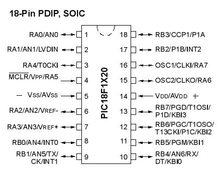
(You'll notice that the pins have multiple names, corresponding to the multiple uses they can have. This PIC has 16 input/output pins, and they're split into "Port A" and "Port B" with 8 pins each.)
Next, we decide whether each pin will be an input or output. (On startup, the PIC makes them all inputs by default.) The DDRB register contains the direction settings for the 8 pins of Port B, and DDRA is for Port A. The numbering is highest-to-lowest, which is standard for binary. So DDRA=0b11111110 will set pins RA7 through RA1 to be inputs, and RA0 to be an output. The "0b" in front tells the C compiler that you're going to write in binary. (A "0x" is for hexadecimal.) Also, note that RA5 can only be an input, as indicated by the arrow in the pinout above. The rest can be configured as either inputs or outputs.
Next we're into the real application code. The first line is LATAbits.LATA0 = 1; this makes RA0 go to +5V (assuming it's been configured to be an output). If we had configured RA0 as an input, and we wanted to read from it, we would use "variable = PORTAbits.RA0". LATAbits is the register of "commanded" pin values. PORTAbits is the register of "sensed" pin values. Warning: the compiler does let you write to PORTAbits to command a pin to change state, but you shouldn't. Always use LATAbits when writing and PORTAbits when reading. Writing to PORTAbits will cause weird behavior.
Next, the loop "while(1){....}" is a continuous loop. Every PIC application will have its code inside such a while loop, so it gets repeatedly executed rather than just running once and stopping. Note that I wrote "1" instead of "true" as in most languages. C18 actually doesn't support boolean variables; it does boolean operations using integers, with 1=true and 0=false.
Inside the while loop, I use the library delays function to delay 0.5 seconds, then I set RA0 to the opposite of what it was. Note that I read from LATAbits.LATA0; that makes the PIC read the commanded value. (It would have also worked to read from PORTAbits. RA0; that would have made the PIC sense the actual value of the pin, which is the same as the commanded value in this case.) After that, the while loop goes back to the top, so the process repeats forever.
Now, change it to your application
If the sample code is working, it's time to make the PIC do whatever you want. For general loops, if/then statements, variables, etc, just use the standard C language. For hardware functions like the serial port, analog-to-digital conversion, etc, look in the C18 Library PDF file to see how to use the functions. The library also has software functions: math, time delays, etc.More sample code:
For code examples of some of those functions in use, see the below files. To use them, I recommend you take your working tutorial project, and go to Project/Save Project As... to make a new duplicate project with a different name. Then, in the project tree under Source Files, right-click tutorial1.c and say Remove, and then add the file you want.
Blinking LED -The code from the tutorial above.
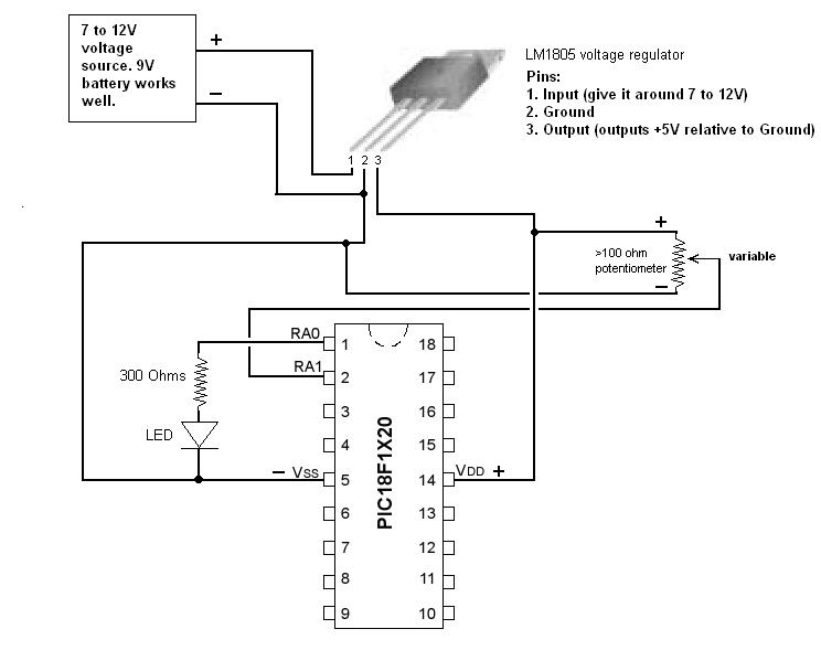
Analog-to-Digital conversion - Demonstrates the ADC ability of the PIC. Use this circuit to test it. The circuit is the same as the test circuit above, with the addition of a potentiometer in a voltage-divider setup. The potentiometer is used to make a variable voltage. Use a multimeter to measure the voltage on the variable lead of the potentiometer; the LED should light when it goes above 2.8V. Note that it may be off a little if your power supply is not exactly 5V. Given a perfect reference voltage, the ADC itself is accurate to within 1 bit, which is about 5mV.
Serial Communications - Reads in a voltage using the ADC circuit above, and then transmits its value through the PIC's serial port. Use the above ADC circuit, with this circuit added on. The MAX232 chip is used to convert the +5V/0V output of the PIC's serial port into the more standard serial port voltages of +/- 10V. You have to give it external capacitors for the voltage conversion, as shown. The datasheet recommends 0.1 to 1uF, but slightly higher values usually work too. For plugging in to your computer, you can order the standard serial "DB9" connectors online; that's what I recommend. For testing purposes, I recommend using the program COMtester to view the data being sent into your computer's serial port. (Also, all of this works perfectly well if your computer doesn't have a serial port and you use a USB-to-serial converter. Note that some converters like to randomly change their COM port, so check for that if COMtester says the port is invalid. You can check it or change it back in Device Manager.)