Newer devices
Starburst Turret
How to build things like this
Robot
About Me
Finding force on an AX-12 leg, using joint torques
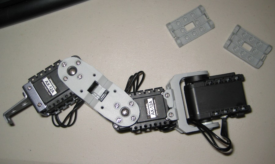
The biggest benefit of the AX-12 servo is that it transmits information about itself such as position, speed, and a rough estimate of torque. You can use this rough estimate of torque to get a rough estimate of the force on the foot of a hexapod leg. (See my earlier page for a description of the AX-12 hexapod leg.)
Background on AX-12 torque sensing: The AX-12 reports its torque as a fraction of full torque. The datasheet is unclear, but we can infer that this torque (called "Present Load" in the datasheet) is really just a report of how much current the AX-12 is feeding its internal motor -- "full torque" means it's feeding full current to the motor. Because there's not actually a torque sensor, this is a very rough estimate of torque: if you just push on the stationary arm, the reported torque will be low, because most of your force is being resisted by friction in the gears of the servo. On the other hand, if you command the motor to push against an obstacle, the torque estimate will be fairly accurate. So, it's not perfect, but it's still very useful to be able to tell how hard the robot is pushing on things, especially when it's free. To convert the reported torque percentage into useful engineering units, you can multiply the torque percentage times the full rated torque from the AX-12 datasheet (12 Kg-cm with 7V power, a.k.a. 1.18 Newton-meters).
The servo for each joint reports the torque on that joint. Now we need to take those joint torques and figure out how much force is being applied to the foot. To do that, we'll have to use math. You can also skip the math and download the relevant functions at the bottom of the page, if your robot arm/leg is similar to mine.
The Math
It's actually fairly complicated math, so we'll take it in steps. All of these are done in my code in a fairly reusable way, so the explanations are just here for purposes of understanding:
1. Given joint angles, find coordinates of foot
This is called forward kinematics, and there's a straightforward (though labor-intensive) process to do it, for any robot arm. It uses the fact that you can convert a point from one coordinate system to another coordinate system (with a different origin and different axis directions) by multiplying the point's coordinates times a 4x4 matrix. The "Denavit-Hartenberg convention" specifies a way to define a coordinate system for each joint in a robot arm, so that you can easily build a matrix to convert from one joint's coordinate system to the next (the matrix will obviously include the joint angle as a variable). Then you multiply the matrices together to do one conversion after another until you've converted the foot's coordinate system into the world coordinate system.
That was just the basic idea of it; it's too involved to cover in detail here. Fortunately, a roboticist at the University of Illinois wrote a Mathematica script called "Robotica.m" that handles the math. (The page that hosted it seems to be down, so here's a mirror.) So now you, too, can solve forward kinematics for an arbitrary robot arm. (You still need to specify the arm in the Denavit-Hartenberg convention; here's a good video and a textbook chapter describing how; a Google search will turn up more explanations.) Here's the Robotica input file which describes the hexapod leg: DHparams.txt. Here's my Mathematica file which uses it.
After all that, the result is a fairly short method called findFootPosition(...) which takes joint angle and does the math to output foot position. It will work for any arm or leg whose joints are configured like the picture above.
2. Find derivative of foot position with respect to joint angle
If a joint moves a little, the foot's x coordinate will move by some amount. For a given leg position, this relationship can be expressed with a simple factor. In other words, if we look at joint 1:
(change in foot x) = (some factor)*(change in joint 1 angle)
You'll have a different factor for each joint's (1, 2, and 3) effect on each foot movement axis (x,y, and z). We can make a 3x3 matrix from these factors, called the Jacobian matrix. (Traditionally, the Jacobian will also include similar factors for angular velocity of the foot, but that's unnecessary in this application.) These Jacobian factors will obviously change with leg position-- for example, if the leg is stretched out all the way, rotating the shoulder by a given amount will produce a larger change in position. So, in that example, the Jacobian factor which converts joint 1 motion into foot x-axis motion will be larger.
The Robotica script discussed above can find the Jacobian analytically by taking the derivative of the "angle-to-position" matrix. The formulas for the Jacobian factors end up extremely long, so I decided to find the Jacobian factors numerically in my program when I need it. I do that by applying a small change in joint angle and using the findFootPosition(...) method to do the forward kinematics and find the resulting change in position. So, by that method, we can find the Jacobian factors for the current leg position.
3. Believe that the Jacobian factors also convert between torque and force
We said this previously:
(change in x) = (Jacobian factor from j1 to x)*(change in joint 1 angle)
It turns out that the factor above also gives us the information we need to convert torque to force. We can prove it using a thought experiment called the Principle of Virtual Work:
- Remember that 1 Newton of force applied for 1 meter of movement = 1 joule.
- Also remember that 1 N-m of torque applied through 1 radian of rotation = 1 joule.
- So if a robot joint applies 1N-m for 1 radian, we know it's done 1 joule of work. Now, suppose the Jacobian factor was 2, so that the foot moved through 2 meters in that time. In that case, we know the force on the foot must have been 0.5 Newtons, from conservation of energy (because 2m*0.5N = 1 J ). The radians-to-meters conversion (Jacobian) was 2, and the torque-to-force conversion was 1/2. So we've found that torque times 1/Jacobian equals force. Or, equivalently:
(joint 1 torque) = (Jacobian factor from j1 to x)*(force in x direction)
We're relating force and torque, so we're almost at the goal.
4. Convert torque to force
The last example was a little oversimplified, because in general the movement of one joint will produce movement in some combination of the x, y, and z directions. Or, equivalently, forces from multiple directions all contribute to joint torque. So in reality, this equation is all we really know:
(joint 1 torque) = (Jacobian factor from j1 to x)*(force in x direction) +
(Jacobian factor from j1 to z)*(force in z direction)
However, we have this same information for joint 2 and joint 3, so we have three equations and three unknowns. (Note that the Jacobian factors are all constants. The x,y, and z forces are the three unknowns and are the same for all three equations. Intuitively this makes sense because, if you're pushing on the foot, all the joints are feeling that force; the fact that one joint is stiff doesn't save the others from feeling the force; they all feel the same force.)
So, my findForce() function uses the Apache Commons math library to solve that system of three equations using the standard matrix inversion method. (It's convenient that we have three joints and three unknowns; if we had a different number of joints we would have to do tricks such as a pseudoinverse matrix.)
And thus, after a lot of work, we have an estimate of the forces!
5. Dealing with complications
There are a couple things that interfere a little with our force calculation:
Complication #1: AX-12 Torque Inaccuracy
The AX-12 torque report is a rough estimate. For example, I've seen it read up to .07N-m when there's no torque being applied. And, depending on the joint position, the Jacobian factors can become sensitive to small errors in torque. My higher-level code needs to know when there's a real force on the foot (such as when the foot is hitting an obstacle), but it needs to ignore phantom forces caused by inaccuracies in the torque. So, my force-finding code deals with this by estimating the "error band" for its calculated forces.
It estimates the error by perturbing the torque on a joint and finding the effect that has on calculated force. Specifically, I assume torque could be inaccurate by up to .07N-m, so I add .07 to the reported torque and then recalculate the foot forces. I repeat this for each joint and add up the force changes to get an estimate of the possible error for each axis of force.
With that error estimate, the higher-level code can tell how reliable the force calculation was. For example, if the x-axis force differs from zero by more than the error band, we know the force is real.
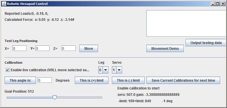
Example: in the upper left of the screen below, the "#" indicates that the calculated z-axis force is far enough from zero that the force is real. (The robot was pushing its foot down into the table when this screenshot was taken.)
Complication #2: Singularities
In certain robot arm positions, there are position changes which cannot be achieved. For my hexapod leg, this happens in the fully extended position (can't move in the direction of extension) and the position where the foot is directly beneath the shoulder (can't move forward-back; can only move up-down and in the direction of the "knee"). These positions are called kinematic singularities, and the cause the system of equations above to be unsolvable (underconstrained, which manifests itself as a matrix with no inverse). My force-finding code just flags these conditions as unsolvable, so higher-level code will know that there's no force measurement available. In practice though, I'll just avoid these positions.
Conclusion
I tested the force calculation with a known 250g weight. The force estimate was within 20% of truth under the optimal conditions, which means far from a kinematic singularity, with the motors actively straining to try to move the weight. If the motors are not actively straining (for example, if I apply the weight while the arm is stationary, rather than having the arm lift the weight) the estimate is generally only within a factor of 2 of truth, because the servos don't detect their own frictional resistance. And near kinematic singularities it becomes very inaccurate. (My "error band" approach properly detects the large error though.) Overall, the system seems to work well enough for un-demanding robot control purposes.
The complete Java code is below; it builds on the code from my last post. It's still a work in progress, so if you're going to use it, email me and I'll be happy to help you understand it:
- Complete Eclipse project: SpiderRobot_with_force_sensing.zip
- Just the java file with the relevant functions: robotControl_forcesensing.java